An I3C IO Bridge Concept for Special Effects Automation using the NXP LPC865
Aug. 24, 2023
Eli Hughes
Introduction
There is a world of sound, lighting and stage production that involves a truly awesome mix of mechatronics, motor control, giant dinosaurs, and rock & roll music shows. Unbeknownst to many, some of the most sophisticated automation systems for lighting, motion, and special effects are designed and engineered in “Amish Country” of Pennsylvania. I recently had an opportunity to visit the headquarters of TAIT towers in Lititz, Pennsylvania and get a tour of some of their latest projects. Their work can be found at live shows for the most popular artists, venues, and attractions. The visit to TAIT inspired some of the concepts in this article and got me thinking about ways to use the new I3C protocol and the LPC865 microcontroller as system IO bridge for professional stage and sound applications.
Theatrical Automation is Powered by Many IO Protocols, Old and New.
The lifeblood in the special effects industry is automation using rugged industrial IO that is stitched together with a blend of both new and incredibly old protocols. There are always advancements in the industry but there are an enormous number of systems using “classic” protocols to make special effects systems function. The NXP LPC865 is positioned to be a great IO co-processing solution to implement some of these lighting and special effects protocols.
In this paper, I will illustrate a use case that utilizes one of LPC865’s most distinguishing features: An I3C interface.
Setting the Stage for the I3C IO Bridge Use Case
One of my favorite NXP crossover MCUs is the i.MX RT685. It offers significant capabilities for audio and DSP applications. It can be a great solution for products that need to tie together real-time audio, lighting, and motion controls. While the i.MX RT685 offers plentiful IO, there are situations where Flexcomm peripherals can get tied up with other implementing features such as high channel count digital audio streams, SPI displays, etc. In some scenarios, it may be simpler to add a low-cost microcontroller to offload timing critical IO operations while the host manages other tasks such as a GUI, DSP or other high datarate tasks. This rationale could also be true for I3C capable applications processors such as the i.MX 93.
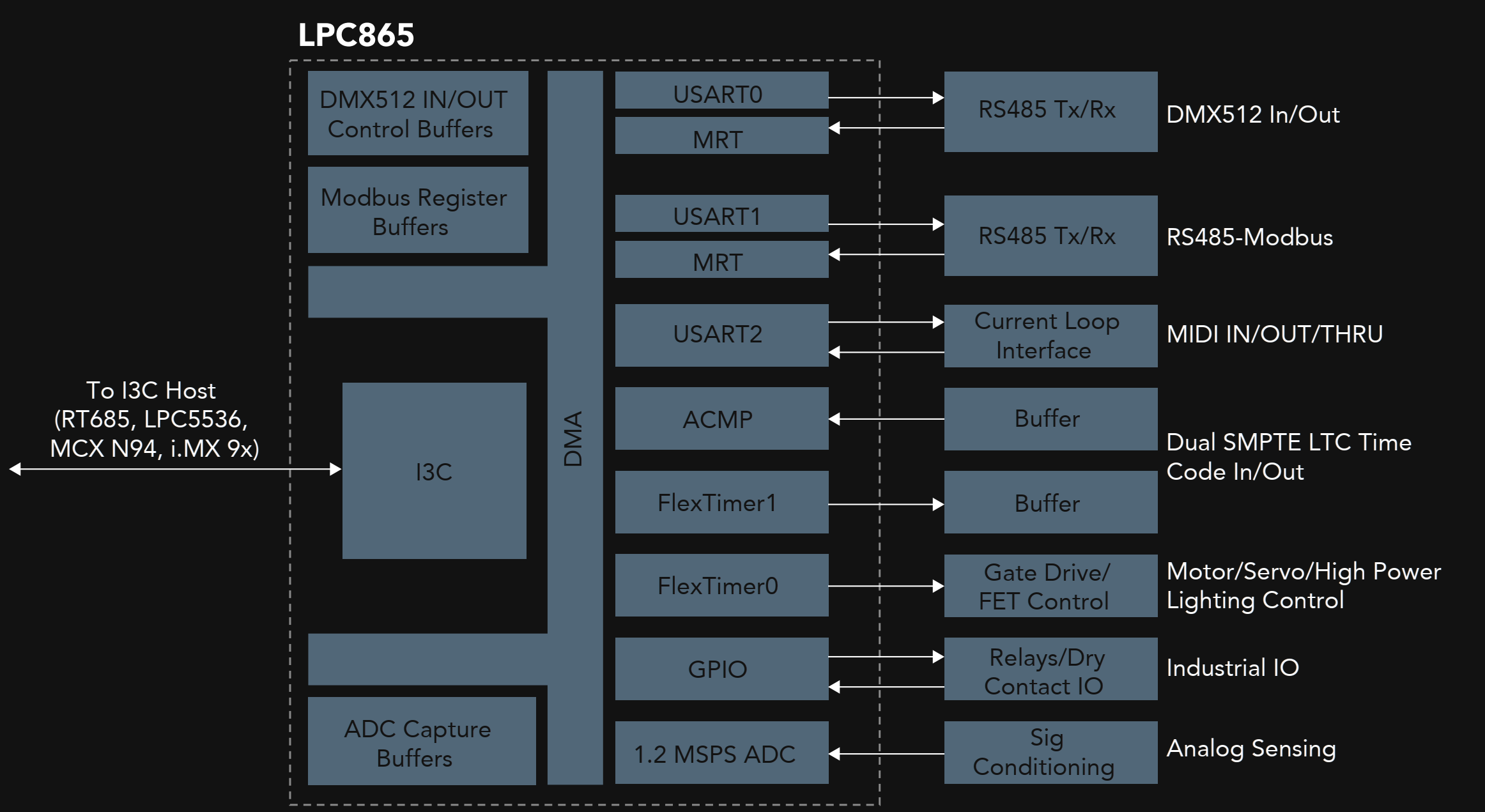
An I3C IO Protocol Bridge for Professional Lighting and Special Effects.
The LPC865 is positioned to be a great IO co-processing solution to implement some of the lighting and special effects protocols. I will be showing the LPC865 as an I3C co-processing solution. However, you will see that it could also be a standalone node in lighting or a motion control network without the need for a host.
I3C is the new I2C
I3C is an enhanced version of the classic I2C two-wire bus. NXP’s ownership of the I2C bus can be traced to its heritage in Phillips Semiconductor. I3C was developed by the MIPI alliance to provide an upgrade to the I2C for higher speed two-wire inter-IC communication applications. I3C is positioned as an alternative to SPI while keeping a simple two-wire interface between devices on a PCB.
Notable highlights:
Backwards compatibility with I2C (7-bit addressed supported and no clock stretching).
Up to 12.5 MHz clock rate. SDA switches from open drain to push-pull for higher data rates. SCL is now always push-pull.
“In-Band Interrupts.” A peripheral can interrupt a controller over the bus without the need for additional pins. Additional context bytes can be added to the interrupt signaling.
Priority mechanism through addressing/arbitration.
Multiple controllers on the same bus.
Dual Data Rate modes (HDR-DDR) that transmit multiple bits per clocking symbol for additional bandwidth.
Hot Joins and dynamic addressing. Target nodes can join the bus at any time. Nodes get notifications when a new device joins the bus.
Common command codes to standardize behaviors.
LPC865 Positioning
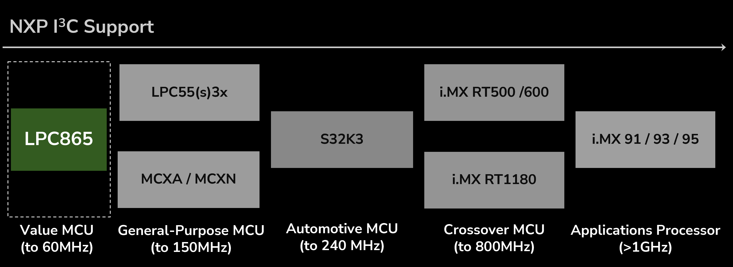
One of the challenges of a new protocol such as I3C is device support. I3C is now supported across a wide range of NXP offerings, from the entry-level parts such as the LPC865 through high-performance applications processors.
NXP MCU/MPU I3C offerings
The I3C peripheral combined with other notable features, positions the LPC865 to be an excellent programmable I3C IO bridge solution. I3C peripherals currently exist on the market in the form of accelerometers, inertial measurement units, and temperature sensors. The affordability, packaging, and peripheral integration of the LPC865 empowers system designers to create I3C peripheral use cases without needing to wait for a solution in the general market. It is common to engineer embedded systems where certain IO functions are offloaded to a secondary microcontroller.
There are many good reasons to split functions across physical devices such as:
IO limitations/peripheral budgeting on a host applications processor.
Isolation of timing/safety critical IO tasks.
Ease of development through the separation of concerns.
Ability to modularize functionality at a physical device level.
System management, watchdog, and boot control.
The I3C capability of the LPC865 enables IO offloading while keeping a two-wire interface that offers:
High data transmission for fast IO and quicker data access as compared to I2C.
In-band interrupts over the two-wire link to notify a host enables a simpler PCB layout.
Multi-controller operation. Roles between the IO handler and the Host can dynamically swap.
I3C by specification can handle up to 11 devices on a two-wire bus, this enables a highly scalable system utilizing the LPC865
Traditional IO expansion and system control applications typically use I2C or SPI as a communications interlink. When higher bandwidth transfers are required for an application, SPI is commonly used. Adding additional SPI peripherals can quickly create wiring challenges as additional chip select and interrupt lines may be required.
I2C is an alternative to SPI when there are lower data rate requirements. The physical layout can be simpler than SPI as only two wires are required to interconnect devices. I3C offers a two-wire bus with significantly improved bandwidth and new features such as in-band interrupts. In addition to I3C support, there are a few other aspects of the LPC865 that support the I3C IO bridge use case.
Physical Packaging, Flexible Switch Matrix, and GPIO
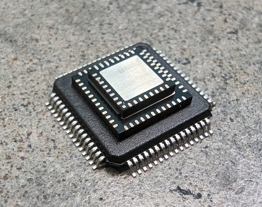
The first order of business when I am considering a new MCU is to understand device packing and IO. The LPC865 is offered in a 10mm2 LQFP64, a 7mm2 HVQFN48, and 5mm2 HVQFN32 package.
LPC865 Packaging.
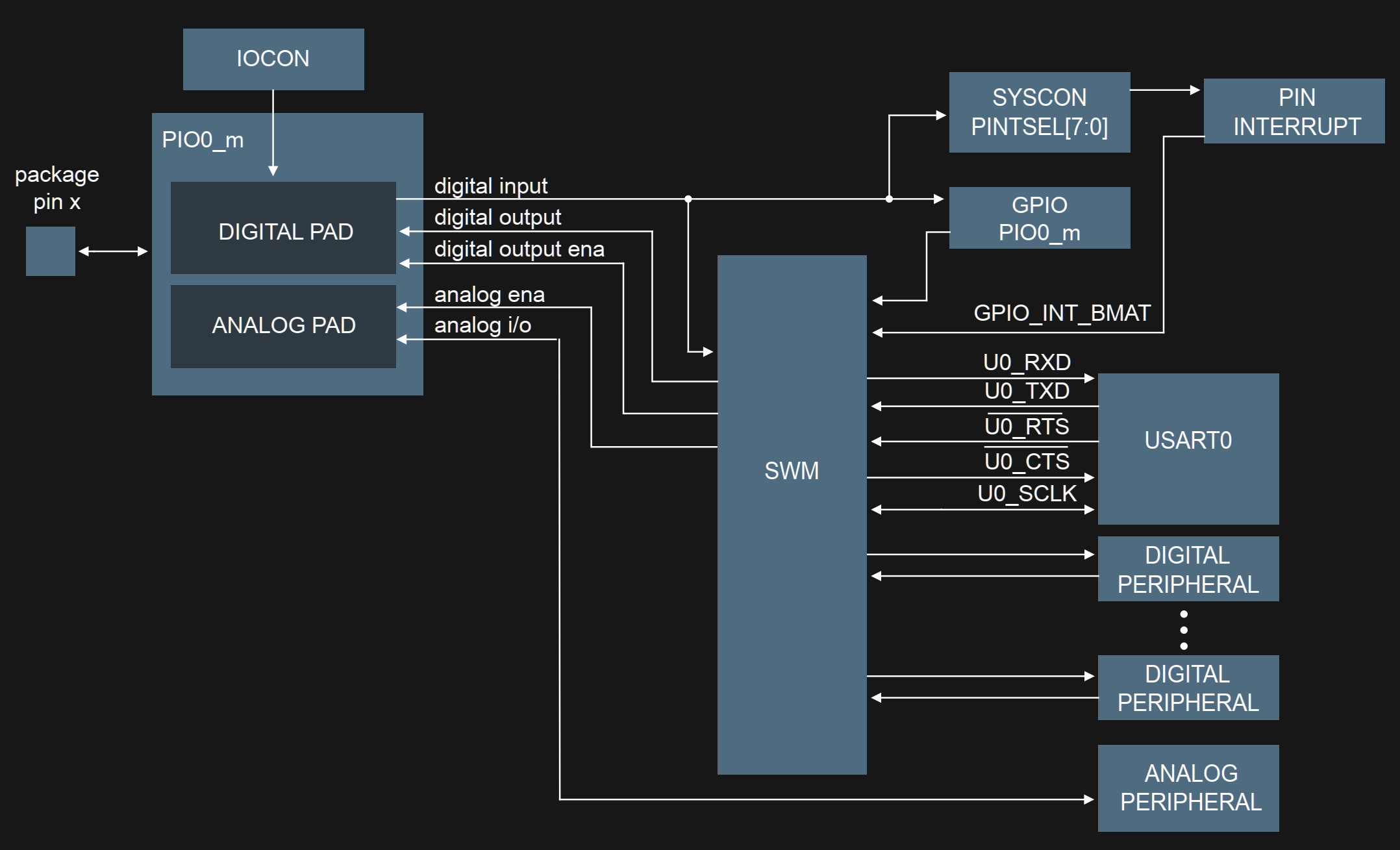
Designed to be pin and IO compatible with the LPC845, the LPC865 packages scale up and down for different levels of IO bridge solutions. A unique IO feature of the LPC865 is the flexible switch matrix (SWM). The SWM enables most of the digital peripherals, including I3C, to be routed to any port pin via the PINASSIGN registers. The Flex Timers are the exception, but their functions can still be routed to a few different pin options.
The LPC865 Switch Matrix (SWM)
The classic Tx/Rx PCB flip-flop error is no concern for the LPC865. Analog and other special functions such as the crystal oscillator inputs are fixed in location. You can find more details in AN13832 “Switch Matrix Usage on LPC86x”
There are four ports PIO0_2, PIO0_3, PIO0_12, and PIO_16 classified as “high drive” which are capable of sourcing 20mA from the IO pad. One last important note about GPIO, especially for use cases where protocols need to be bit-banged, GPIO operations can be quite fast.
GPIO registers are on the Arm® Cortex®-M0+ IO bus for the fastest possible single-cycle access.
I/O timing, allowing GPIO toggling with rates of up to 30MHz.
An entire port value can be written in one instruction.
Mask, set, and clear operations are supported for the entire port
Sleep and Powerdown Modes
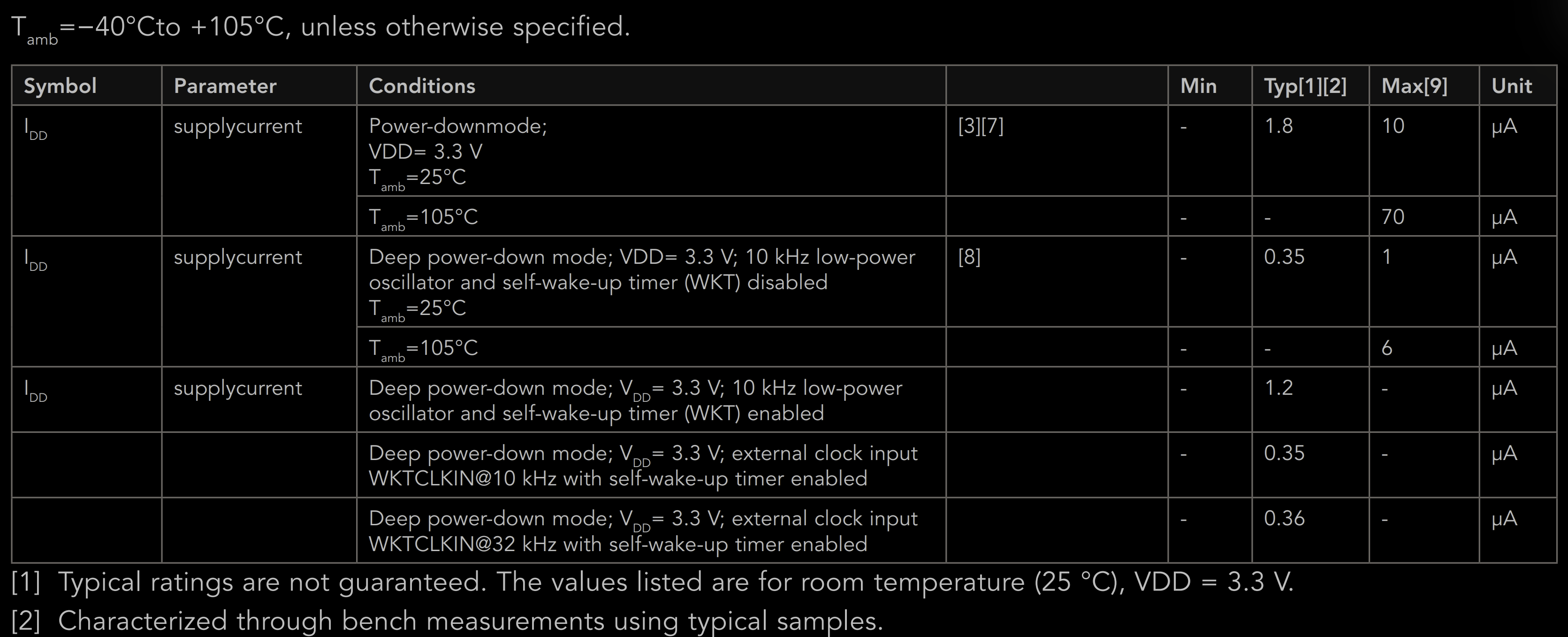
A distinction between the LPC865 and other entry-level CM0+ parts is support for exceptional sleep/power modes. When used as an IO expander/peripheral bridge, the ability to enter a low power state is important for battery powered applications. The power-down and deep power-down in the LPC865 exhibit excellent static performance characteristics.
LPC865 Power-down and Deep Power-down Sleep Currents
ROM Bootloader and In-System Programming Over UART0
The LPC865 has a bootloader that allows flash programming operations over UART0. At reset/power-up, PIO1_12 is sampled. If pulled low, the ROM will enter ISP mode and will accept programming commands over UART0. All the ROM flash API functions are available in the application code, including invoking the ROM bootloader from the application code.
Flash is structured for small 64-byte pages, allowing for simple partitioning of the code and device DNA/factory constant storage. The ISP entry, flash programming, and SWD interface can be locked down/disabled via the Code Read Protection (CRP) mechanisms. The UART ISP / Bootloader makes it possible for a host controller to update the LPC865 in the system without having to write your own bootloader. Application note AN13815 shows how the LPC865 can be updated over it the UART interface by a LPC55S36 MCU.
The ROM bootloader speaks to the IO expander/bridge use case the device could be firmware upgradable without needing to write a secondary bootloader. However, there are application notes on implementing a secondary bootloader function of I2C (which could be extended to I3C).
High-speed ADC, Analog Comparator and DMA
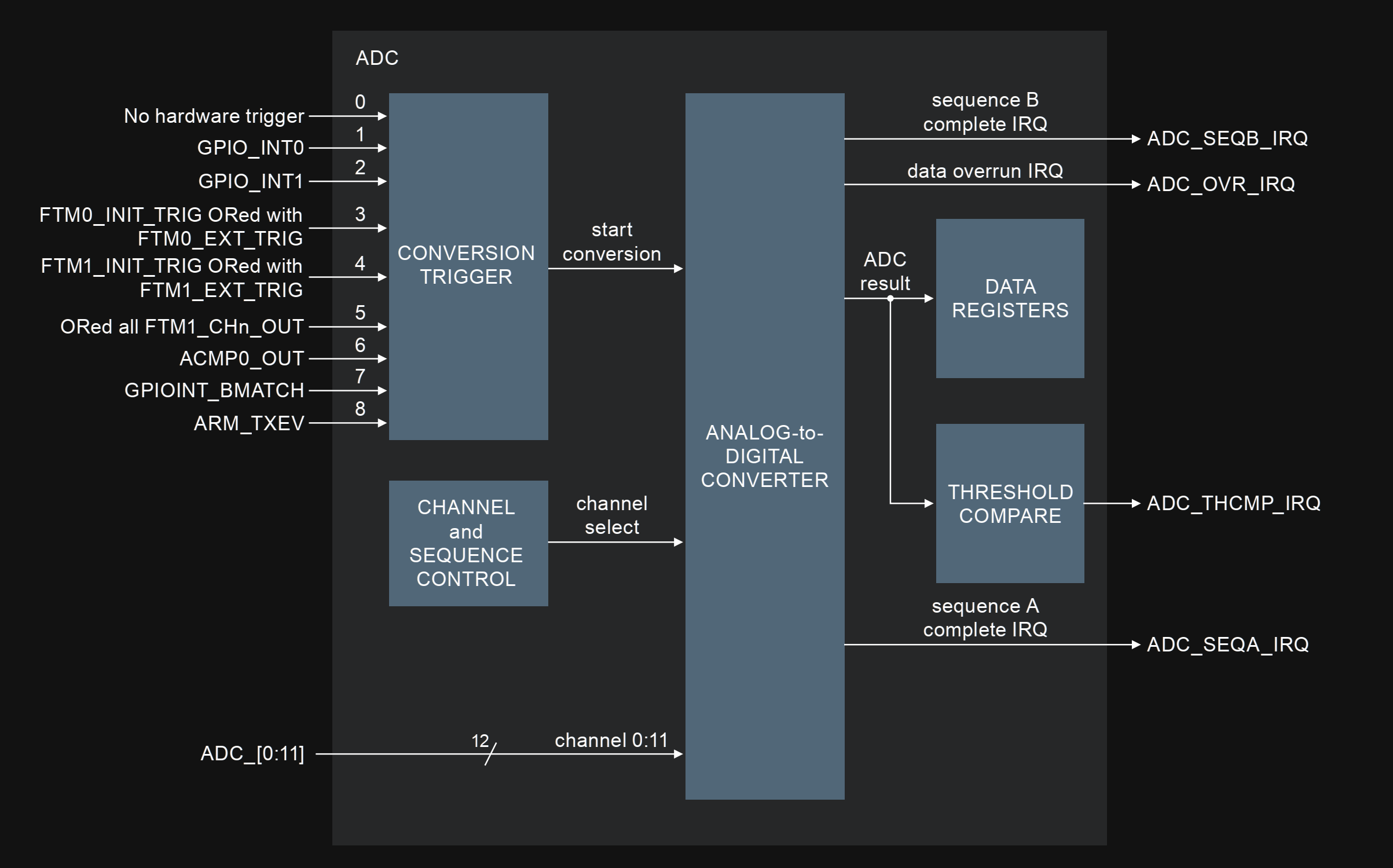
The last three features that make the LPC865 an attractive option for an I3C IO bridge is the combination of 1.9MSa/sec 12-bit ADC, analog comparator, and a DMA controller.
The LPC865 12-bit 1.9MSa/s ADC
There have been many occurrences where I needed to add additional analog functions into a design which required adding an ADC external to the primary microcontroller. It is possible to consider the LPC865 as an intelligent external analog to digital converter peripheral. The DMA subsystem allows fast ADC captures into a memory buffer, which can be transmitted over the I3C link.
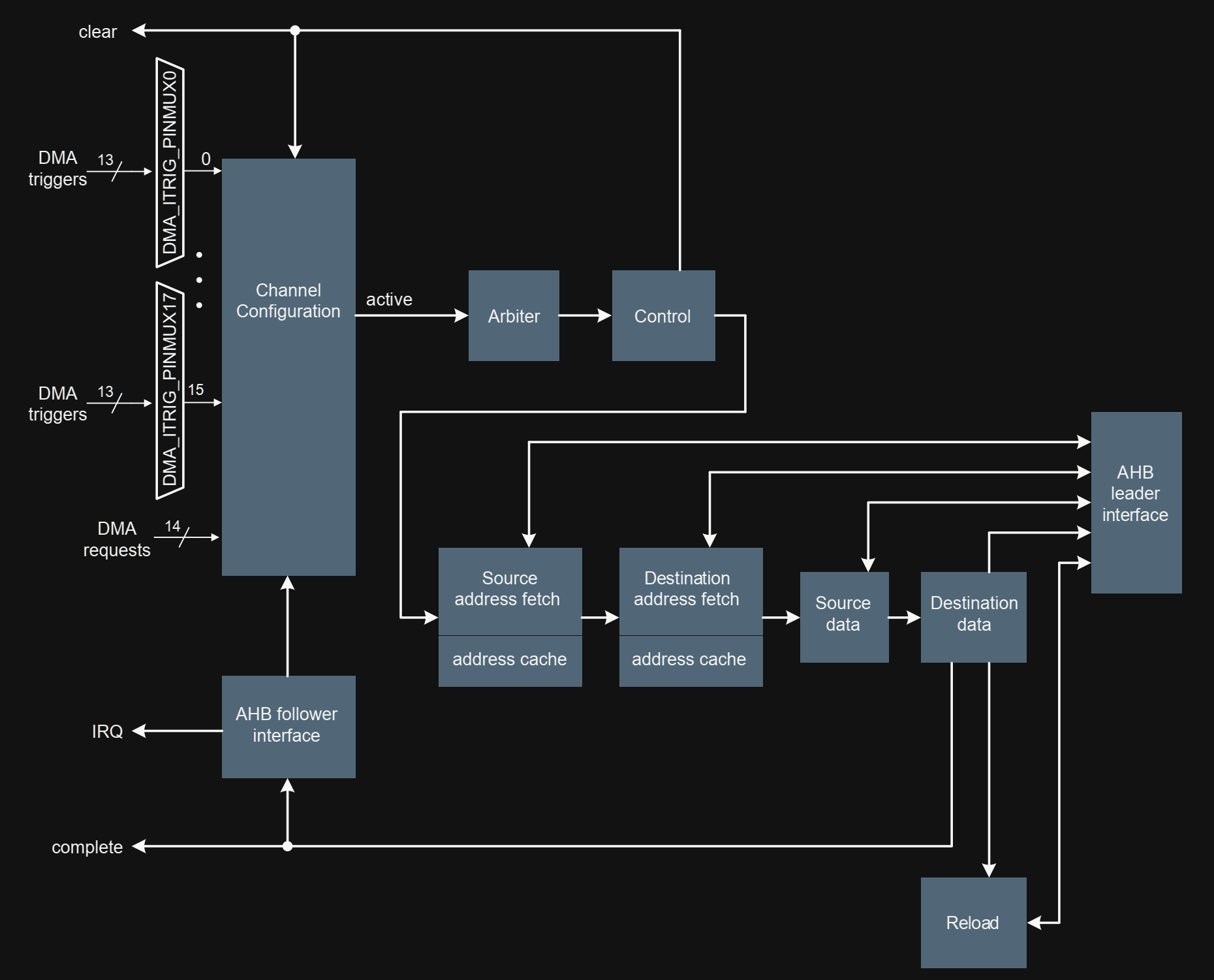
The LPC865 DMA controller
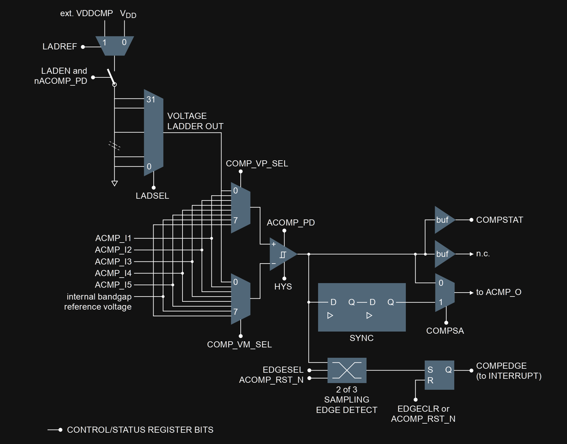
The analog comparator with 5-bit ladder DAC can be used to trigger sampling events. This is in addition to a multitude of trigger options available from the FlexTimer peripherals.
LPC865 Analog Comparator.
I3C to DMX512
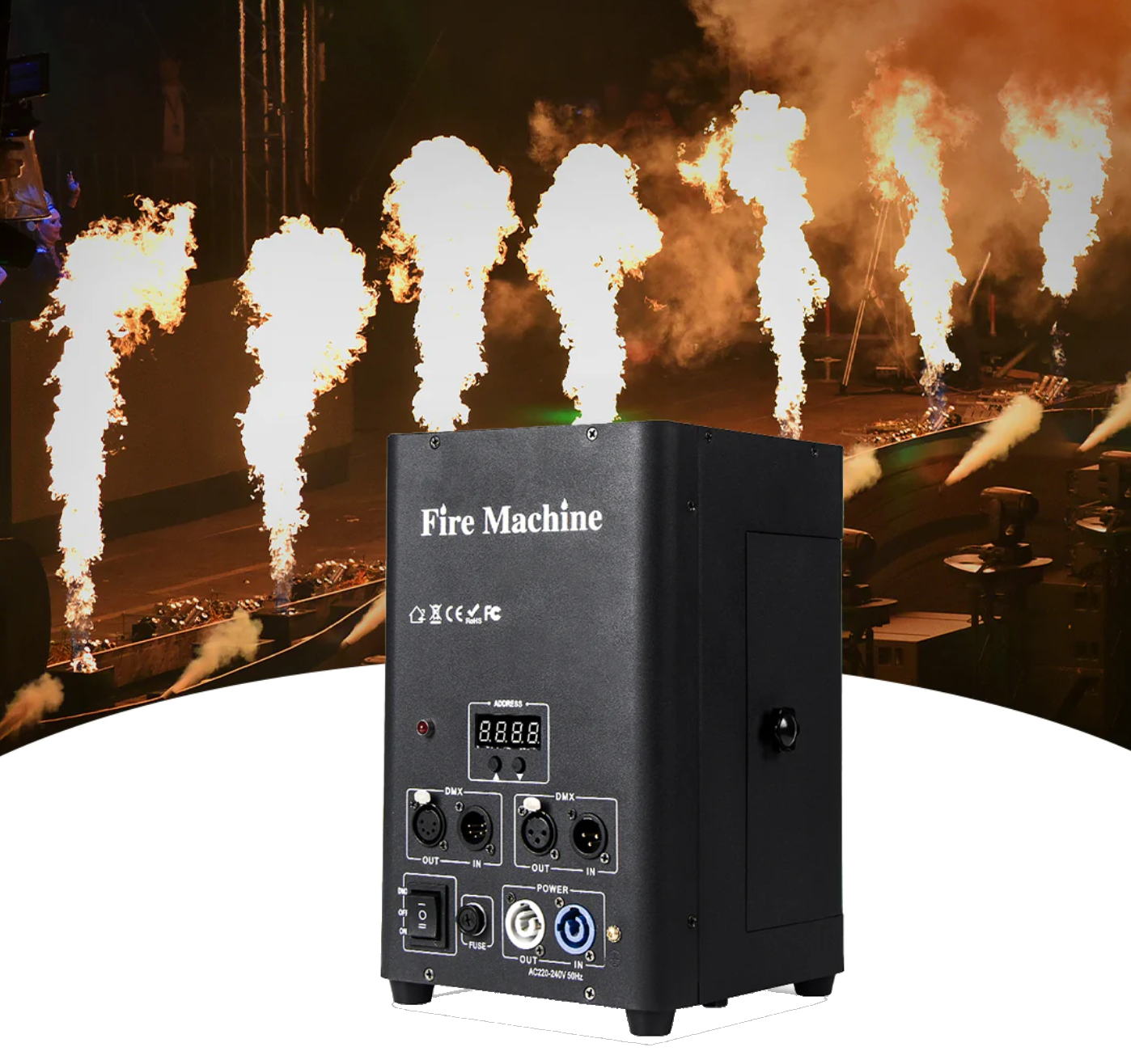
DMX, or DMX512 is a standard for stage lighting, effects, and motion controls. The specification is freely available. DMX512 is a 250 kbps network that uses RS485 signaling. A DMX512 “universe” has 512 channels, or slots, of 8-bit control data. Nodes are daisy-chained on the RS485 network and each node listens for its specific channel control data.
A node may consume one or more slots in the DMX universe. The 8-bit control data can be mapped to lighting levels, motor speeds & positions, or even run special effects such as fog machines and flame throwers.
MOKA SFX DMX Flame Thrower
The 512 control channels are streamed continuously at a constant framerate. In some scenarios, the frame rate is synchronized to other systems such as a video broadcast stream. Data bytes over the DMX512 network are transmitted with an ordinary UART (8 data bits, 1 Start, 2 stop bits). Frames are delineated with a special timed break signal. The LPC865 can implement a DMX512 transmitter or receiver with little CPU interaction using the combination of a USART peripheral, Multi-Rate Timer (MRT), and the DMA controller.
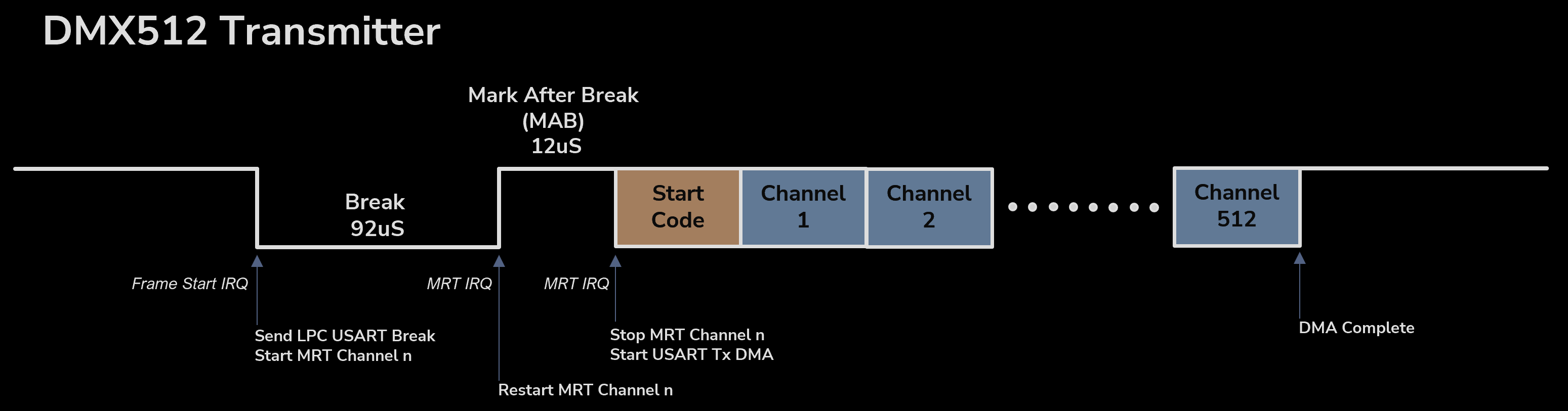
A skeleton implementation of the DMX transmitter in the LPC865 could look like this:
DMX512 Data Transmission
The start of a DMX512 frame is flagged by a break condition for a minimum period of 92uS. Frames are transmitted at a constant rate, for example, 30 frames per second. The frame start flag/interrupt could be from another timing source such as another periodic timer interrupt or from external timing reference such as the SMPTE timecode that will be described in the next section.
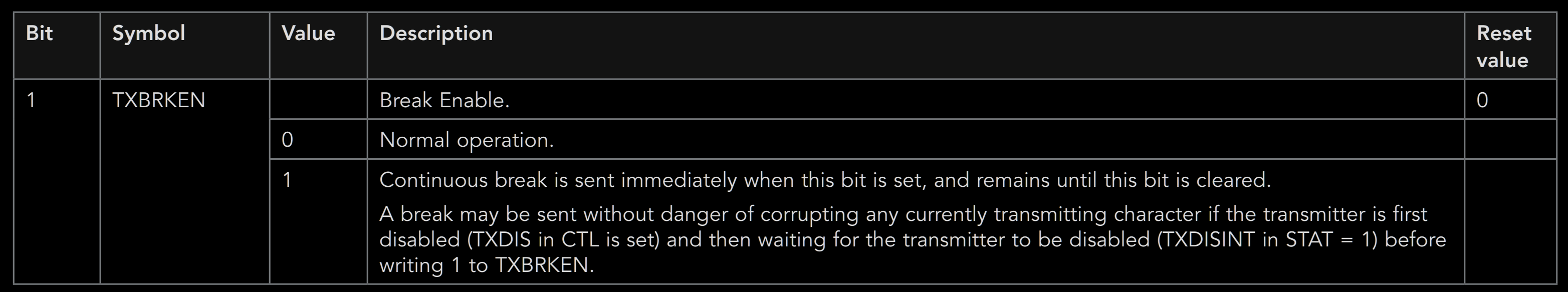
The LPC865 USART peripheral can generate the break condition via its CTL register:
Once the break is initiated, it can be cleared after the minimum 92uS period using a channel of the Multi-Rate Timer (MRT) Peripheral.
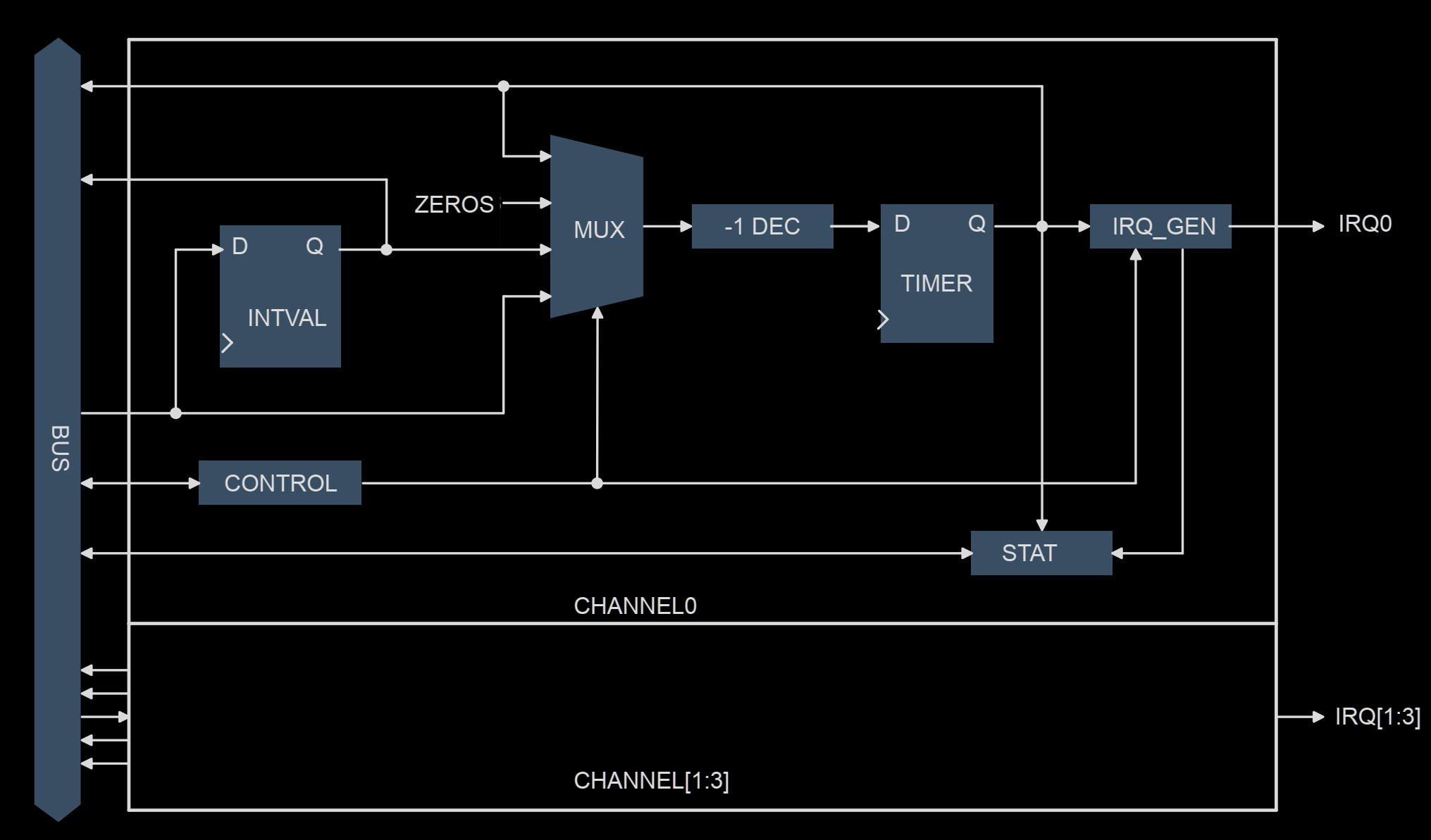
LPC685 Multi-Rate Timer (MRT)
The primary advantage of the MRT is its simplicity. The MRT is a simple down counter that can generate interrupts periodically or in a one-shot mode. Once the break period is complete, another MRT one-shot operation can flag the “Mark After Break” (MAB) period. After the MAB, the DMA controller is used to transmit a start code and 512 control values from a RAM buffer. This approach chains three peripherals together to transmit one DMX frame with minimal CPU intervention. To implement a DMX receiver, we can make use of the break detection features in the LPC865 USART:
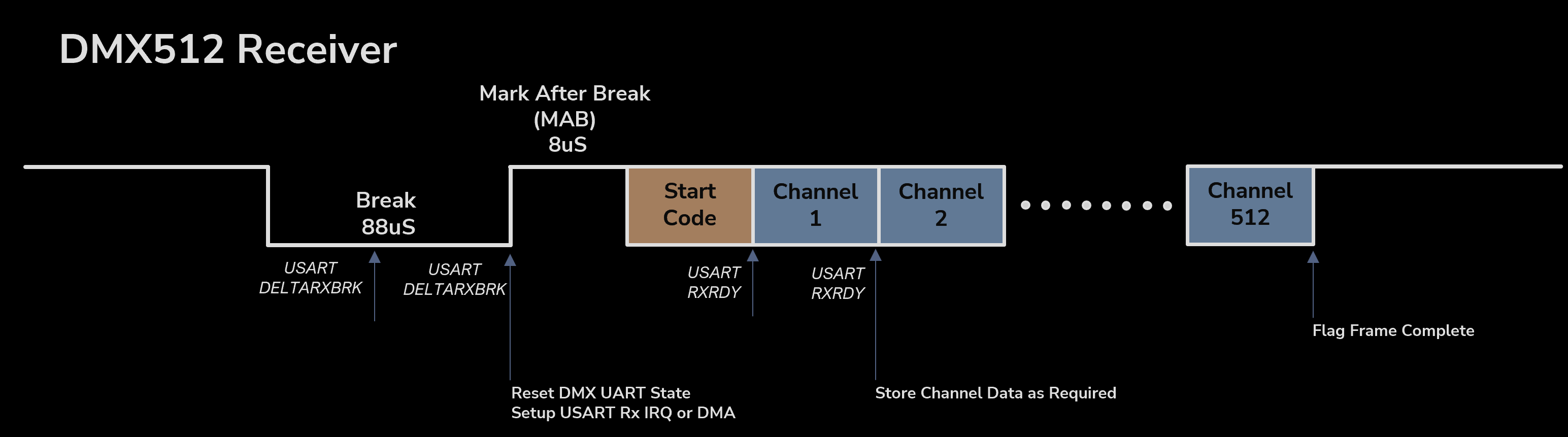
DMX512 Data Reception
The DELTARXBRK interrupt can be used to detect the start of a new frame and reset any frame detection logic. Once a break condition is detected, per character IRQ processing or a DMA operation can be used to read the incoming frame data. An additional timer peripheral can be added into the mix to measure the total break period if the receiver needs to filter out invalid/minimum break conditions.
Note that the official DMX512 specification has break and MAB periods that are 4uS (one-bit time of 250KB/s) shorter than a transmitter. DMX is a continuously streamed protocol. Using I3C as the link to the host processor, it is possible to continuously update the entire DMX universe frame by frame with I3C bandwidth to spare for other IO bridge functions.
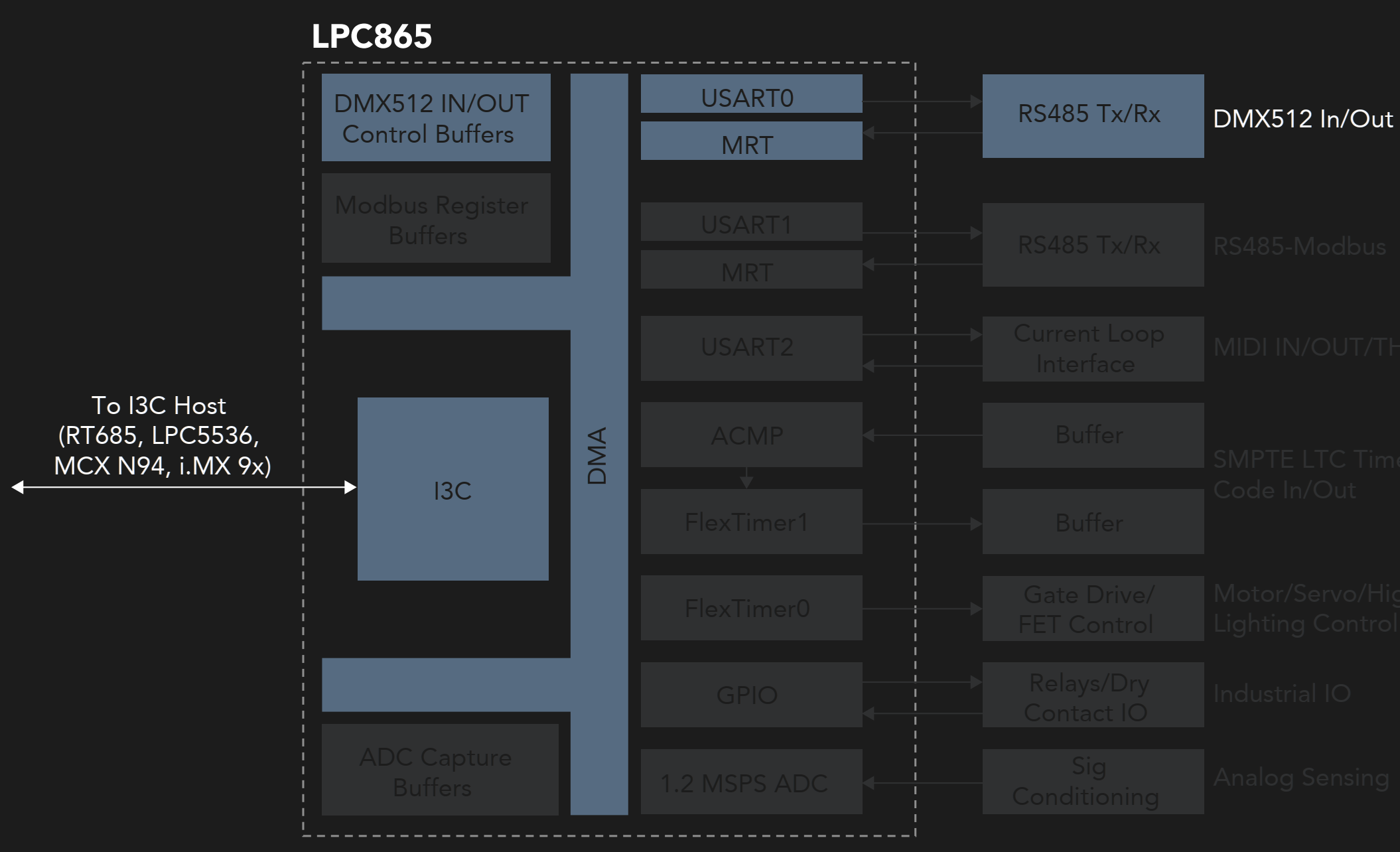
I3C to DMX512 Dataflow
In the context of our bridge concept, RAM buffers store the DMX universe data that the I3C interface interacts with. I3C in-band interrupts can be employed to notify the host processor when data for the next frame is to be transmitted. When using DMA controller in conjunction with the UART and MRT, DMX512 data can be transferred between the interfaces with little CPU intervention.
I3C to SMPTE Timecode
In lighting control and automation systems, different functional systems are sometimes synchronized with a timecode signal. The Society of Motion Picture and Television Engineers (SMPTE) developed a timecode labeling system that has become ubiquitous in the video production industry. SMPTE timecode, also known as linear (LTC) timecode, is a method of labeling frames such that it is simple to scrub to a specific part of a video.
SMPTE Timecode on a clapperboard. Photo CC BY 2.0 Licensed.
If you ever see a rolling timecode on a video, chances are it is SMPTE timecode. This SMPTE frame labeling system became a way of synchronizing video systems. As a result of its ubiquitous usage in video media, SMPTE timecode has found its way into related industries as a method of synchronizing lighting and motion control systems.
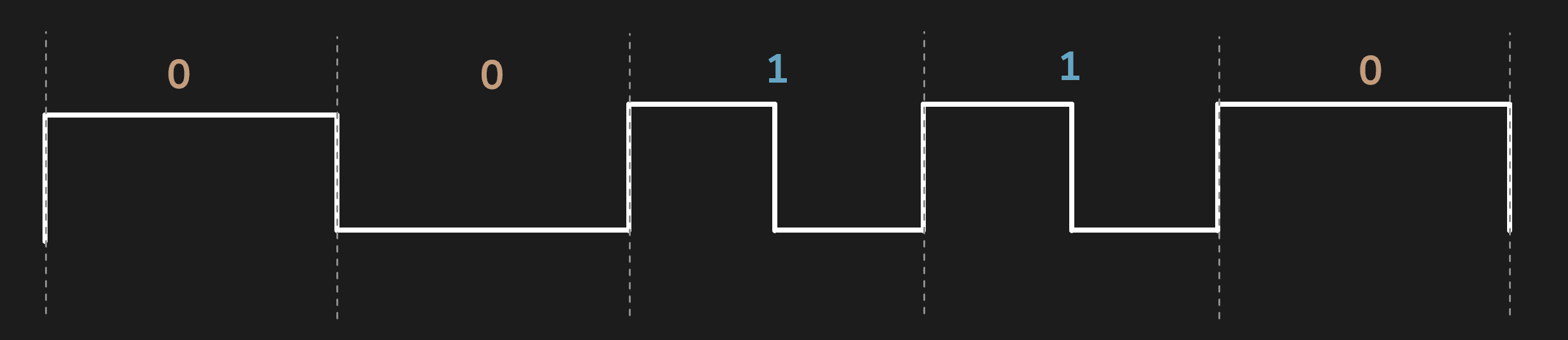
SMPTE timecode was designed for film to be replayed to a predefined rate. Timecode information is encoded into each frame of the film that indicates hours, minutes, seconds, a frame number as well as some ancillary/user data. Bits of SMPTE timecode data are encoded as a biphase mark code code. The number of transitions in a time period indicates a “1” or “0” in the bitstream.
SMPTE Timecode Biphase Mark Encoding
SMPTE timecode is represented as 80 bits of data stretched over one frame period. To synchronize receivers, a fixed bit pattern is placed at the end of each 80-bit frame. The synchronization symbol enables a receiver to establish a baseline period for the incoming transitions to be able to distinguish a “1” from a “0”. The biphase mark code was used as video and its associated audio/ancillary was orginal encoded onto magnetic tape.
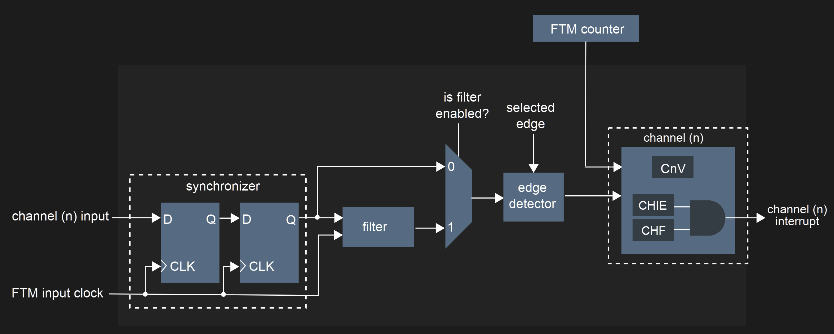
To decode an SMPTE timecode signal with the LPC865, we can use one of the Flex Timer Modules (FTM) input capture functions.
LPC865 FTM Input Capture
The FTM input capture module can register the value of a counter on the edges of the incoming digital waveform. The detection algorithm can successively measure the period between the edges to determine the baseline bit period. Once this baseline period is established, bits in the SMPTE stream can be decoded and shifted into the synchronization detection logic.
Since there is a distinct synchronization word built into each SMPTE frame, the firmware can continuously keep in sync with the incoming stream on a frame-by-frame basis. Decoding of different frame rates is straightforward with the FTM. Software logic can continuously look at the time between edges to determine the active frame rate and adjust the decoder.
SMPTE timecode is typically transmitted as an analog signal on conventional audio cables such as ¼”, RCA or balanced line XLR. To bring the SMPTE signal into the LPC865, the built-in analog comparator can be used to convert the analog biphase code into a clean logic signal for the FTM input capture.
Combined with the glitch filters in the IO pads as well as the input capture filter, one can have a robust SMPTE timecode detection system with minimal external components other than protection circuitry and an analog buffer.
The LPC865 could also generate SMPTE timecode signals. Using an FTM channel, the biphase signal can be synthesized from a precomputed 80-bit frame. This could be helpful in applications where a DMX output needs a frame synchronized to a SMPTE timecode.
I3C to MIDI
The MIDI standard was developed in 1983 as a method of interconnecting electronic musical instruments. While originally intended for transmission of musical note events and timing, the control messages have been used for non-musical applications. Because of the ubiquitous availability of MIDI control surfaces, there is an ecosystem of MIDI controllable products (lighting, motion controls, etc.) that have a connection to audio synthesis. SMPTE timecode messages can even be carried across a MIDI link.
Waterworld Attraction Synchronized by MIDI Show control. Photo CC BY-SA 3.0
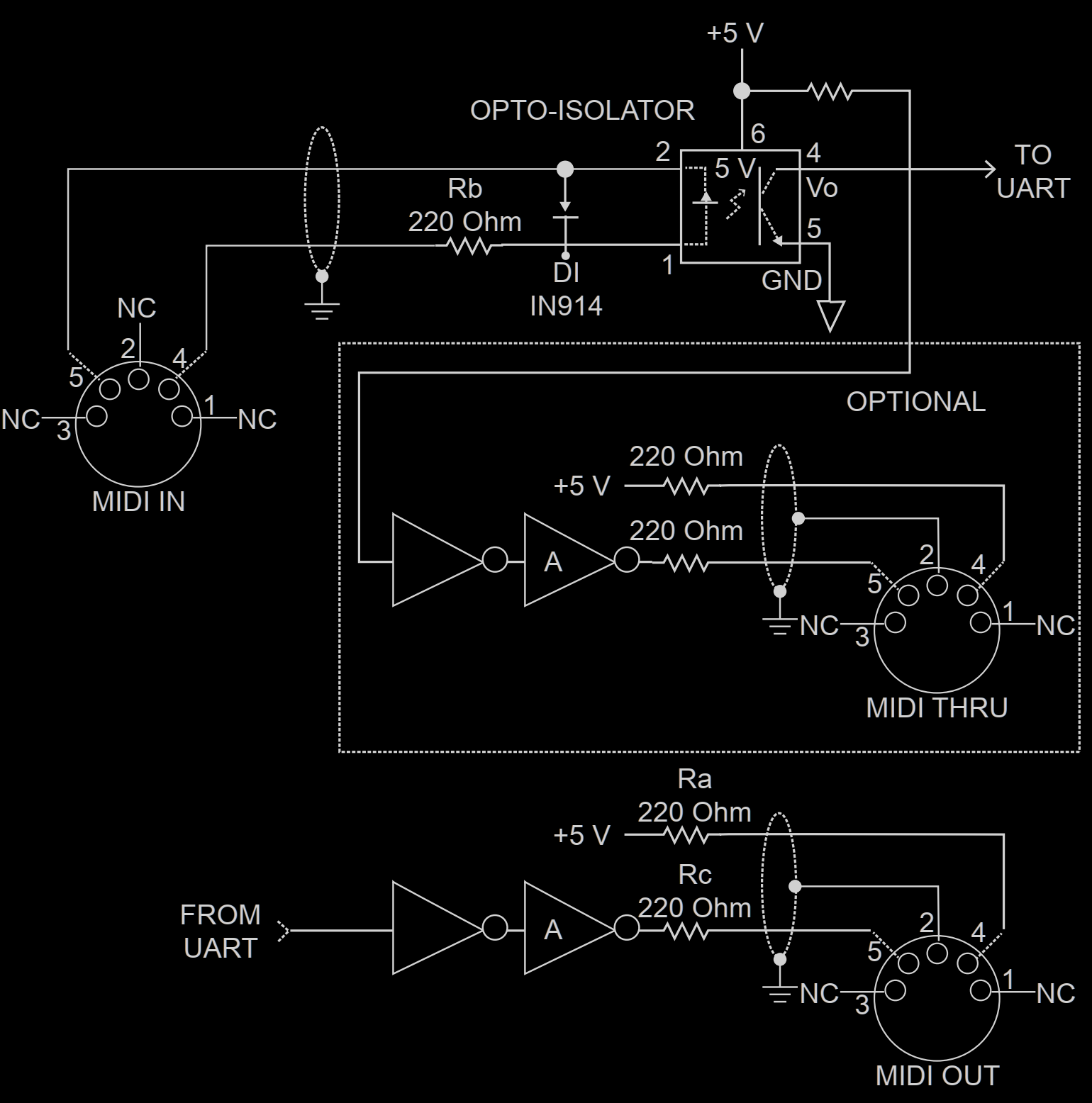
A MIDI link is an opto-coupled current loop driven by a UART at 31250 baud.
MIDI Physical Interface from the MIDI 1.0 Specification
The MIDI 31250 baud is not a common value that is not always directly achievable by typical clock sources and integer dividers. However, all three UARTS in the LPC865 share two fractional dividers (FRGs). The FRGs are to achieve nonstandard baud rates with minimal timing error. Adding MIDI to the I3C bridge is straightforward with one of the UARTs and the fractional divers to hit the correct baud rate. Adding MIDI IO to the I3C bridge is straightforward with the LPC865’s builtin UART and FRGs.
I3C to MODBUS RTU - RS485
Modbus is an open, de facto standard protocol in industrial sensing and control applications. What makes Modbus so ubiquitous is its simplicity in its message framing and data model. Modbus uses a client-server approach with half-duplex communications.
The utility of Modbus comes with its simple data model. Each device implements an array of 1-bit (Coils/Discrete Inputs) and 16-bit entities (Holding Registers/Input Registers). Coils (1-bit) and Holding Registers (16-bit) have read/write access while Discrete Inputs (1-bit) and Input Registers (16-bit) are read-only. The server can map the Discrete Inputs and Coils to actual physical IO (for example a relay) or a “virtual operation” (an internal configuration setting). Analog input data from sensors can be placed in the input registers.
This model is extremely simple and effective for the industrial use case and Modbus is an integral part of industrial programming paradigms. Most Programmable Logic Controllers (PLC) implement Modbus. There are a substantial number of Modbus devices available on the market ranging from simple sensors to complicated actuators and motor controls. Industries such as stage lighting, effects, and performance use a PLC together disparate systems to implement an overall choreographed performance.
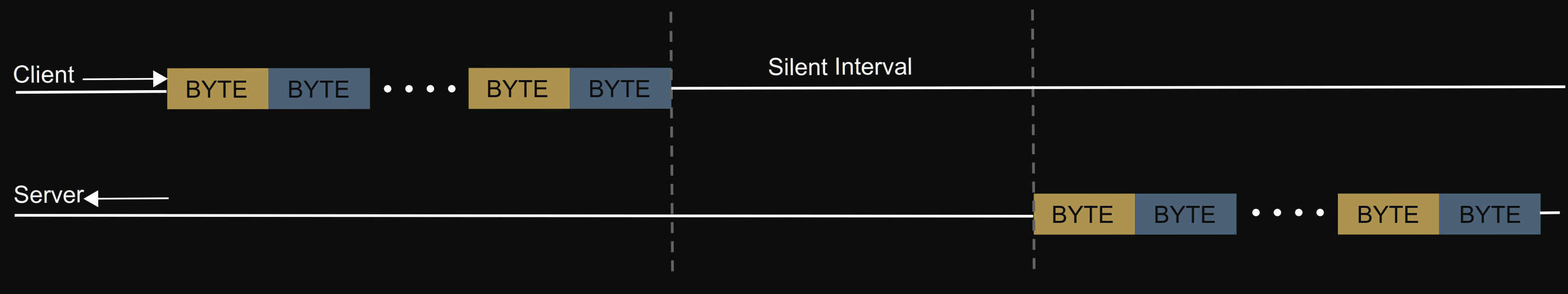
Adding Modbus RS485 to our I3C bridge solution is straightforward with another UART instance and MRT channel. Modbus data packets, or PDUs, are simple binary packets transmitted via RS-485 signaling. What makes Modbus different from other serial protocols is that data packets do not have explicit “end of frame” or “start of frame” bytes.
Frames must be sent as back-to-back characters. The end of a packet is delineated by *idle time*. This means that in addition to a UART, we need a timer to properly implement Modbus-RTU. The Modbus specification indicates that there should be a minimum of 3.5-character times (19200 baud and below) or 750uS (>19200 Baud) to delineate packets.
Modbus Message Delineation
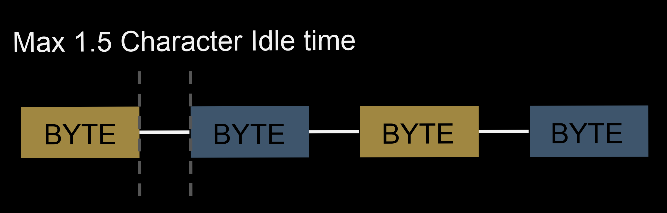
Modbus assumes 11-bit characters: 1 start-bit, 8 data-bits, 1 parity, and 1 stop-bit. In the case of no parity, 2 stop bits are specified. Modbus also specifies that there should never be more than 1.5 characters of idle time in bytes in a packet.
Modbus Inter-character Timing
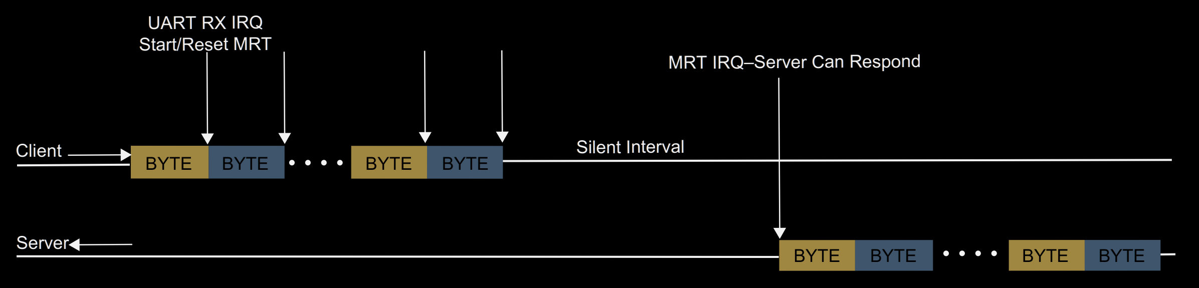
As packets are delineated by idle time, a timer is required to detect the end of a packet. Like the DMX512 implementation,we can use an MRT channel to meet the packet timings. For detecting Modbus packets, we can use the MRT interrupt with a UART receive interrupt.
Decoding Modbus Packets with a UART and MRT IRQ
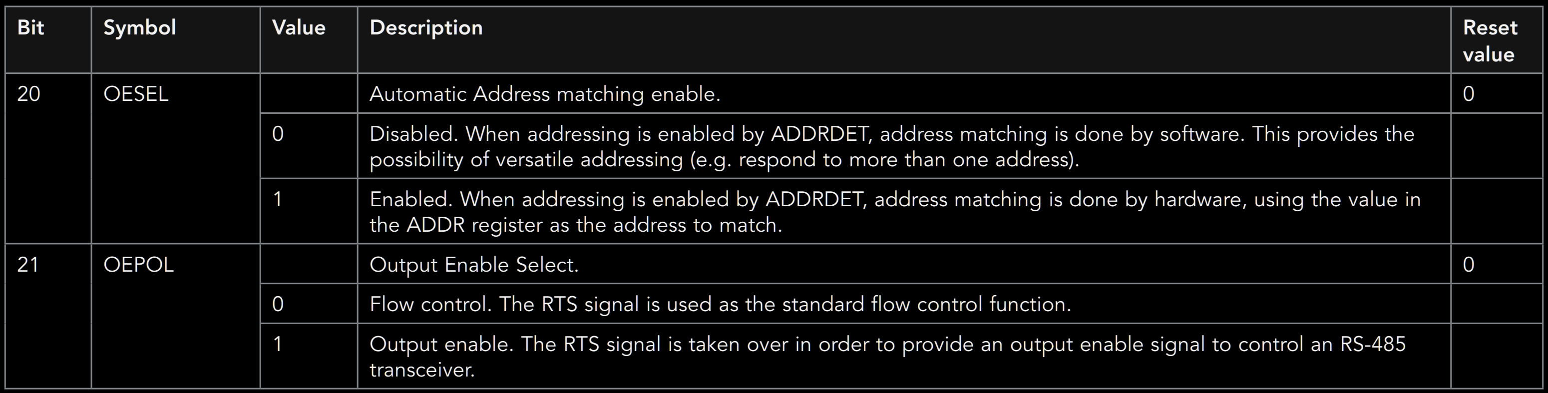
The LPC865 UART peripheral can automatically control the direction of an external RS485 transceiver for half-duplex operation.
LPC865 UART RS485 Transceiver Direction Control.
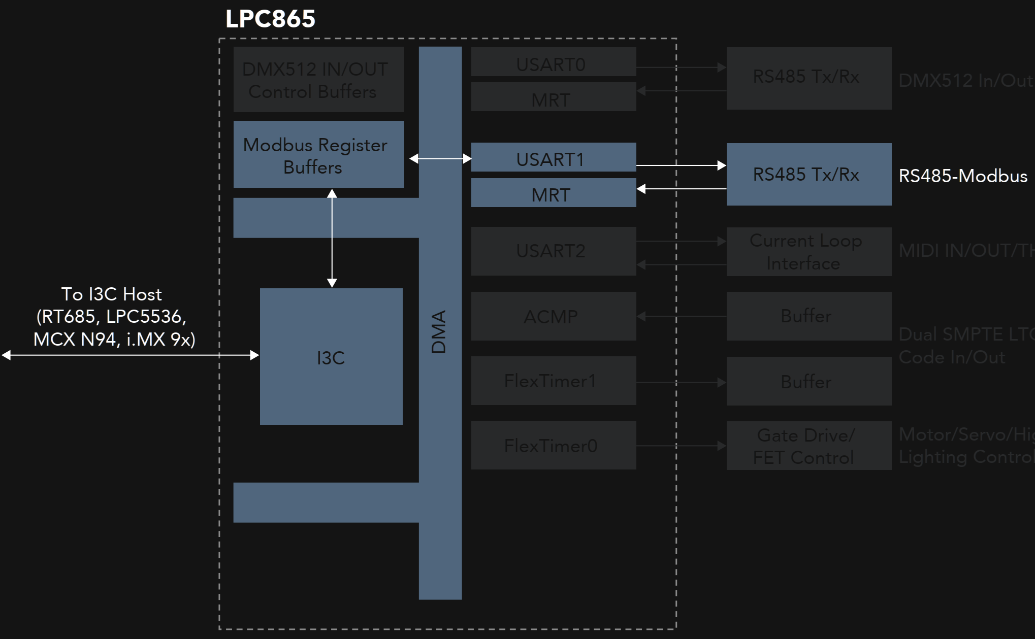
In the context of our I3C bridge concept, the Modbus register map can be exposed over an I3C interface. The LPC865 can manage the timing and interface details of the physical RS485 interface.
I3C to Modbus Dataflow
I3C to PWM, GPIO,and Analog Sensors
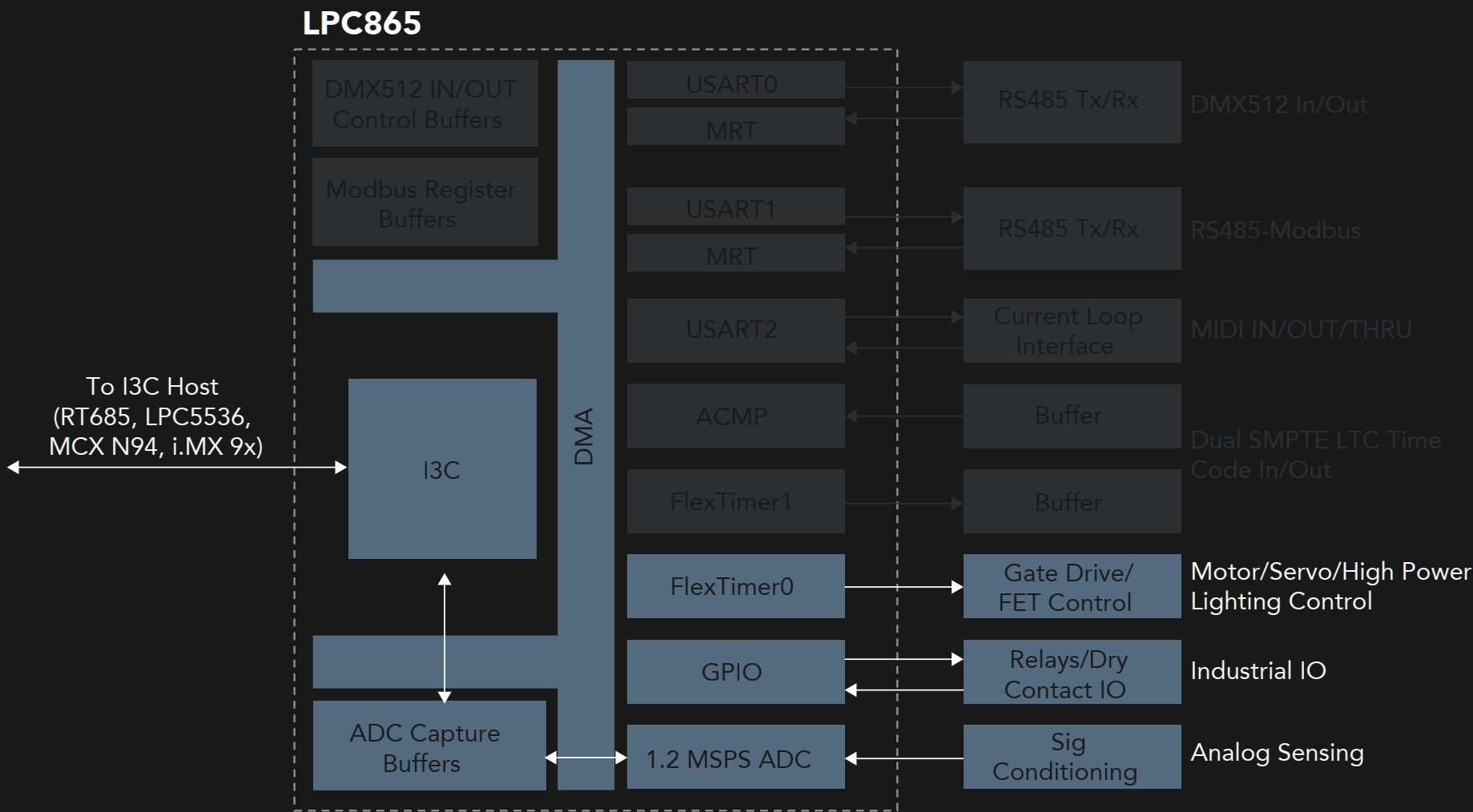
Even with all the domain specific interfaces, there are plenty of pins to add additional general-purpose IO to the bridge solution. This could include banks of relays to control electrical power systems, PWM outputs for high power lighting channels, electromechanical servos, or current drive solenoid values. Between the two FTM peripherals, one can get up to 10-PWM outputs if they are not used for another purpose.
I3C Bridge to Analog, PWM, and GPIO
Motor control is a primary application for the LPC865 ADC subsystem. However, the ADC could also serve as a generalpurpose interface to measure industrial sensors such as 4-20mA transmitters for pressure, temperature, flow, etc. Once a designer’s mind is opened to the possibilities, there are quite a bit of industrial control applications for the LPC865.
Final Thoughts
In this paper, I presented the LPC865 as an I3C IO bridge solution. Even though the context in this article was for an IO bridge to a host MCU, onecan see that the LPC865 could be utilized as a standalone. The application presented here focused on interfaces specific to stage lighting, motion controls, and special effects. However, replacing “Modbus” with “BACnet” and “DMX-512” with “DALI-2” in transforms the LPC865 into a solution for distributed lighting, sensors, and controls in a build automation system.
Some other potential use cases for the LPC865:
Dedicated system controller, battery charger, power supply sequencer, and system Watchdog.
Intelligent multichannel ADC with the ability to buffer and transfer over two-wire I3C.
I3C to Sensorless Field Oriented Control for BLDC and PMSM motors
I3C to HUB75 LED 32x32 pixel matrix display controller
With its low cost, flexible IO, and small package options, the LPC865 can be useful in many contexts.